News
Storm Direct Shipping Product (DSP) Study – Supporting Information
INTRODUCTION
The Storm Copper Project is located on Somerset Island, Nunavut in the Canadian Arctic Archipelago, within the Cornwallis Fold and Thrust Belt. The Project is part of the Aston Bay Property, which includes Storm Copper, the Seal Zinc Project, and numerous regional prospects and targets.
On March 9, 2021, TSX-listed Aston Bay Holdings Ltd. (Aston Bay) entered into an option agreement with American West Metals Limited (American West), and its wholly owned Canadian subsidiary Tornado Metals Ltd., pursuant to which American West was granted an option to earn an 80% undivided interest in the Project by spending a minimum of CAD$10 million on qualifying exploration expenditures. The parties amended and restated the Option Agreement as of February 27, 2023 to facilitate American West directly earning an interest in the Project alongside its Canadian subsidiary without any change to the overall commercial agreement between the parties. The expenditures were completed during 2023 and American West exercised the option. American West and Aston Bay have formed a 20/80 unincorporated joint venture.
GEOLOGY AND MINERALIZATION
The Aston Bay Property, including the Storm Copper Project, lies within the Cornwallis Lead-Zinc District, which hosts the past producing Polaris Zn-Pb mine on Little Cornwallis Island. The Property covers a portion of the Cornwallis Fold and Thrust Belt, which affected sediments of the Arctic Platform deposited on a stable, passive continental margin that existed from Late Proterozoic to Late Silurian. Southward compression during the Ellesmerian Orogeny (Late Devonian to Early Carboniferous) produced a fold and thrust belt north and west of the former continental margin, effectively ending carbonate sedimentation throughout the region. This tectonic event is believed to have generated the metal-bearing fluids responsible for Zn-Pb deposits in the region.
Storm Copper is interpreted to be a sediment-hosted stratiform copper sulfide deposit, broadly comparable to Kupferschiefer and Kipushi type deposits. The Project comprises a collection of copper deposits (Cyclone, Chinook, Corona, and Cirrus) and other prospects and showings (including the Thunder and Lightning Ridge Zones, Cyclone North and Gap Prospects), surrounding a Central Graben. The Central Graben locally juxtaposes the conformable Late Ordovician to Early Silurian Allen Bay Formation, the Silurian Cape Storm Formation, and the Silurian Douro Formation, and was likely a principal control on migration of mineralizing fluids. The Storm Copper deposits are hosted within the upper 80 meters of the Allen Bay Formation and to a lesser extent in the basal Cape Storm Formation.
The Storm Copper sulfide mineralization is most commonly hosted within structurally prepared ground, infilling fractures, and a variety of breccias including crackle breccias, and lesser in-situ replacement and dissolution breccias, with a relatively impermeable “cap” of dolomicrite (fine-grained dolomite) of the Silurian Cape Storm Formation.
Mineralization at Storm Copper is dominated by chalcocite, with lesser chalcopyrite and bornite, and accessory cuprite, covellite, azurite, malachite, and native copper. Sulfides are hosted within porous, fossiliferous units and are typically disseminated, void-filling and net-textured as replacement of the host rock. Crackle, solution and fault breccias on the decametric to metric scale represent ground preparation at sites of copper deposition.
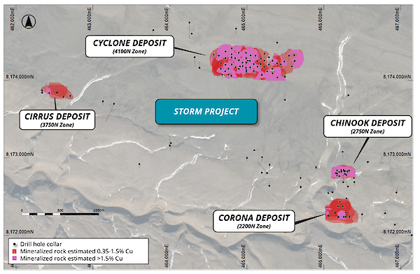
Figure 1: Plan view of the copper mineralized zones for the Storm Project overlaying aerial photography.
DSP BACKGROUND: EARLY TEST WORK CONFIRMS UPGRADE POTENTIAL
Two small-scale ore sorting tests were completed during 2022 and 2023 on drill core samples of high-grade copper mineralization from the Cyclone and Chinook Deposits (see April 11, 2022 Aston Bay press release) to determine whether the mineralization was amenable to ore sorting. The tests were completed using a full-scale ore sorter and confirmed the excellent ability to upgrade the Storm mineralization by successfully producing a commercial grade (DSP.
Whilst the initial studies were highly successful using high-grade copper mineralization, further tests were required to determine the upgrade potential of more representative, moderate-grade mineralization.
METALLURGICAL SAMPLE SELECTION AND COMPOSITING
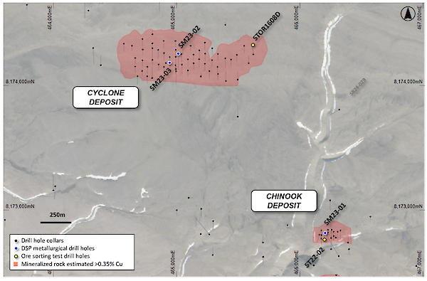
Diamond drilling was used to produce metallurgical samples for the ore sorting and beneficiation/Dense Media Separation (DMS) test work from each of the Cyclone and Chinook Deposits. Three diamond drill holes were completed to provide the material for compositing (Figure 2). The composite samples are considered representative of typical copper mineralization within the Storm deposits. The location of the recent and previous metallurgical drill holes is shown in Figure 2.
The drill holes were completed within key locations of the Cyclone and Chinook Deposits, with NQ-sized ¾ core (i.e. ½ core + ¼ core) retained in the core trays after extracting ¼ core samples for assay.
The sample compositing and assaying were completed by ALS Metallurgy in Kamloops, BC, Canada.
Intervals were selected by the Company’s geologists based on the drill core assays to generate representative grade-targeted composites. For each grade category:
- The +26.5mm sample was generated from breaking up (not crushing) the ½ core.
- The 26.5mm – 11.2mm sample was generated from lab crushing and screening ¼ core from the same sections and screening out the <11.2mm fines.
Figure 2: Metallurgical drill hole locations within the Cyclone and Chinook Deposits.
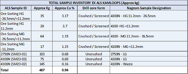
Four composites were constructed for the ALS/Sacre-Davey ore sorting test work, three with differing copper grades, and the fourth classified as waste and put aside for future tests. A description and designation of these composites is in Table 1.
The composite samples for testing were designated HG (High-grade at 3.17% Cu), MG (Medium-grade at 1.15% Cu), and LG (Low-grade at 0.68% Cu). The waste material also contained minor amounts of copper with a grade of 0.16% Cu.
Table 1: Summary of the sample composites for the Sacre-Davey ore sorting test work.
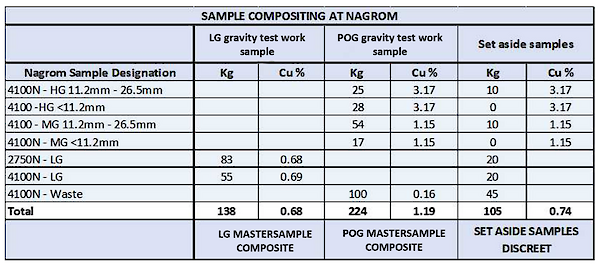
For the next phase of the concept study and DSP test work, the original Sacre-Davey HG, MG, and LG composite samples were recombined to generate new bulk samples to test the upgrade potential of the mineralization with more targeted potential mining grades. This was completed at the Nagrom laboratory in Perth, Australia. The two new master composites were designated POG (Potential Ore-grade at 1.19% Cu) and LG (Low-grade at 0.68% Cu). The left-over material was put aside for further test work and had an average grade of 0.74% Cu.
Table 2: Summary of the sample composites for the Nexus-Bonum ore sorting and beneficiation test work.
ORE SORTING OPTIMIZATION TEST WORK – ALS / SACRE-DAVEY
The objective of the ALS Metallurgy / Sacre-Davey Engineering (ALS/SD) study was to evaluate the feasibility of using ore sorting at a range of copper grades and to determine the most effective sensor(s) and particle size fractions that provide the most promising pre-concentration results.
The study was carried out using 250 rock samples obtained from the Cyclone and Chinook Deposit sample composites (Figure 3). The samples, obtained from ALS Metallurgy - Kamloops, BC, were provided in size fractions of +26.5 mm and -26.5/+11.2 mm (described in the previous section).
The major test program components included ore sorting technology sensor testing of rock samples to assess the amenability of the technology through particle sorting, followed by the assaying of each rock sample. Lab-scale sensor testing evaluated XRT (X-ray transmission), XRF (X-ray fluorescence), and EM (Electromagnetic) sensors across nine sorting scenarios for both high-grade and lower grade sample composites. The re-assayed head grades of the high-grade and lower grade samples were 1.726% Cu and 0.942% Cu, respectively.
An additional sorting scenario was explored for a low-grade composite sample with a head grade of 0.65% Cu. This low-grade composite was created by randomly selecting 65 low-grade rocks from the high-grade and low-grade composites with the intent of making a low-grade sample of ~0.65% Cu.
With the goal of producing DSP with a grade of approximately 20% Cu, the study focused on determining if this targeted product grade could be achieved.
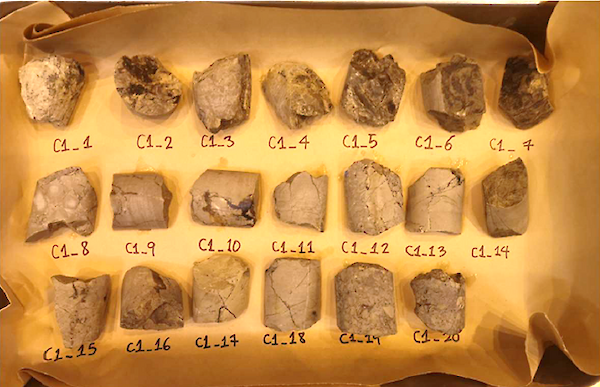
Figure 3: Example of copper mineralization from the Cyclone and Chinook Deposits that was tested by Sacre-Davey.
Results indicated that XRT and XRF can produce sorter concentrate meeting the target grade with promising recoveries and mass pull rates when sorting the -26.5+11.2 mm size fraction of the Storm copper mineralization. However, the coarse size fraction (+26.5mm) proved less amenable to sorting and requires further comminution processing
The study also found that head grade influences sorting potential, with higher-grade composites showing greater potential of meeting the targeted product grade, and that the XRT sensors performed better than the XRF due to its penetrative nature, requiring less feed preparation prior to sorting.
The results from the ALS/SD study were used to guide the next phase of study work which included assessing a detailed process and beneficiation study. The results from the ALS/SD work were included in the final concept study calculations.
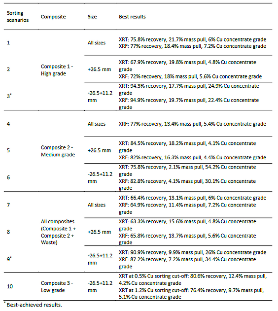

Table 3: ALS/ Sacre-Davey ore sorting test results.
DSP METALLURGY SAMPLE TEST WORK
Nexus Bonum was assigned to supervise further test work and to complete a concept study based on the findings to produce a commercially viable copper DSP.
Pre-concentration Technology Test work
The initial test work carried out by Sacre-Davy confirmed that the copper mineralization was amenable to x-ray sensor (XRT) particle sorting and could effectively upgrade the mineralized material.
A subsequent detailed program by Nexus Bonum, in liaison with American West, tested the sample composites using a range of technologies which included:
• Particle sorting by Steinert at their Perth-based facility using a KSS1000, XRT unit;
• Fines Jigging (to complement particle sorting) at Nagrom, Perth;
• Dry jigging test (Alljig test unit);• Wet jigging test (Alljig); and,
• Wet jigging by OEM Gekko Inline Pressure Jig (IPJ).
The results of the test work indicated that all of the tested processing techniques could upgrade the Storm mineralization, and that there is a direct correlation between copper grade and upgrade performance. The higher the copper grade, the coarser the sulfide veining, and therefore the easier it is to liberate the sulfide particles from the host rocks (dolomite) within a specified particle size distribution.
The Bond Ball Mill Work Index tests were used to determine the hardness and grindability of the two composite samples. Both composites are described as ‘soft,’ with the high-grade sample returning an index of 8.65, and the lower grade sample returned an index of 9.59.
Of all of the tests completed, ore sorting by XRT and wet jigging using the IPJ produced the most favourable results, and the combination of the two circuits allowed both the coarse (>11.2mm) and fine fractions (<11.2mm) to be processed effectively reaching the goal of a DSP product of approximately 20% Cu concentrate grade.
Ore sorting
The concept study ore sorting tests used a full scale Steinert KSS KLI XT machine located in Perth, Australia. The tests were conducted on the -26.5/+11.2mm size fraction of the MG (1.07% Cu) and LG (0.83% Cu) composite samples (Re-assaying of the MG and LG composite samples for this work returned grades of 1.07% Cu and 0.83% Cu respectively).
The bulk testing comprised four steps:
• Steinert hand-selected mineralized rock (indicated by dark sulfide particles) and waste (indicated by veinless light grey material).
• Steinert scanned the hand selected samples through the combination sensor sorter, taking measurements from all four sensors to develop and refine the sorting algorithm.
• The hand-selected and bulk materials were recombined into their respective composites and tested with three ‘cut’ points to produce three concentrates and one tailings fraction.
• All four sort fractions from both composites were dispatched for assay analysis.
The results confirmed that all of the Storm copper mineralization is extremely amenable to ore sorting using the Steinert KSS technology, and that high recoveries can be obtained in very low mass yields (Figure 5).
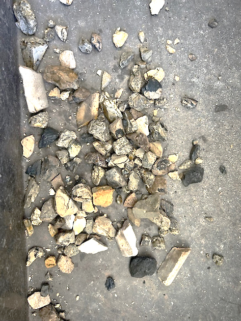
Figure 4: Photo of a high-density cut using XRT ore sorting of -26.5/+11.2mm low-grade composite material. This sample returned a grade of 15.2% Cu from a feed head grade of 0.78% Cu. Note the dark grey/black particles which are chalcocite (copper sulfide), veinlets of chalcocite within most of light grey host rocks (dolomite).
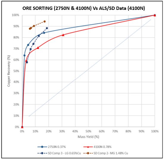
Figure 5: Ore sorting mass flow vs recovery curves for the Cyclone (4100N) and Chinook (2750N) Deposits.
Inline Pressure Jig (IPJ)
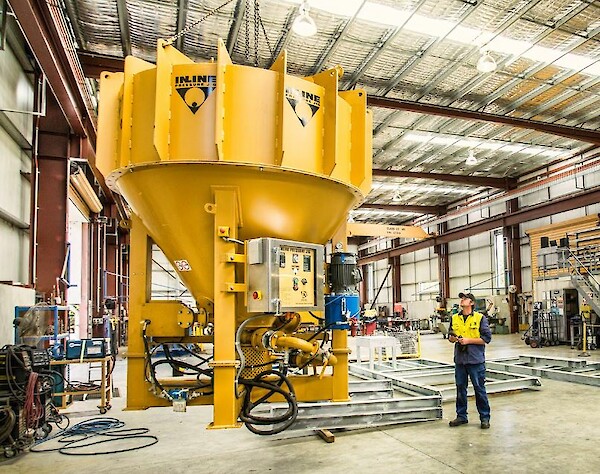
The wet jigging tests were completed by Gekko Systems using a Dense Media Separation (DMS) Viking on the -11.2/+2.46mm size fraction of the OG (1.07% Cu) and LG (0.83% Cu) composites, with DMS testing using a Wilfley table on the <2.46mm material. The technology uses gravity recovery to liberate dense material (copper sulfide) from less dense host rocks (dolomite) due to specific gravity (SG) differences The DMS Viking is used for the test work as the performance and recoveries are comparable to the plant scale Gekko Inline Pressure Jig (IPJ).
The IPJ is an effective and efficient gravity device that is used for processing a wide variety of minerals. The pressurized design and advanced control systems give it many advantages including high recovery, high throughput, low water use (closed circuit with <5% water loss), and close control under operating conditions.
The tests were run at specific gravities (SG) of 2.9, 2.85, 2.8, 2.75 and 2.7, to determine the ideal mass pull vs concentrate grade, and to generate yield vs recovery curves.
The results confirmed that both the POG and LG composites are extremely amenable to processing using gravity-based technology (Figures 7, 8 & 9). However, due to the fine grain size of the very low-grade copper sulfide mineralization, the process can be sensitive to slight changes in SG at lower copper grades.
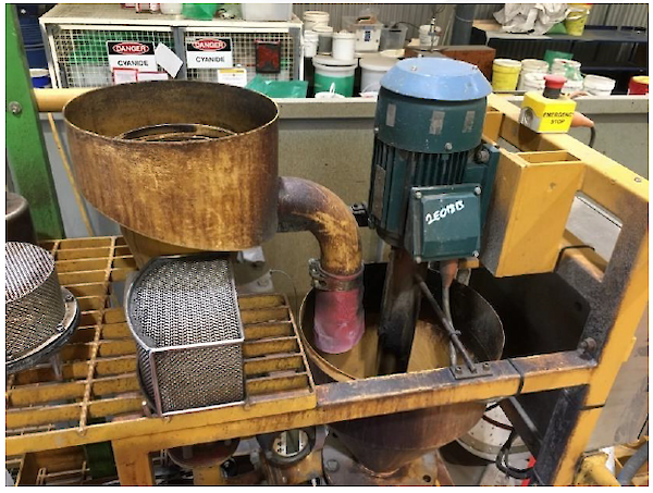
Figure 6: Dense Media Separation (DMS) Viking Cone at the Gekko laboratory.
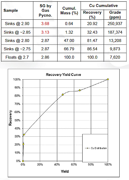
Figure 7: DMS Viking (Inline Pressure Jig) yield vs recovery curves for the Potential Ore-grade (POG) sample.
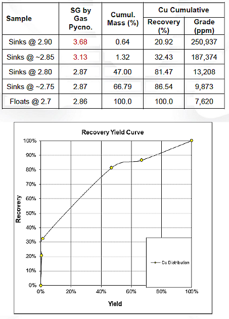
Figure 8: DMS Viking (Inline Pressure Jig) yield vs recovery curves for the Low Grade (LG) sample.
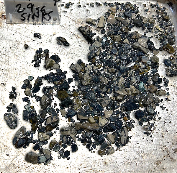
Figure 9: Photo of a DMS Viking product on -11.2/+2.46mm Potential Ore-grade (POG) composite material. The density cut is at a 2.9 SG and returned a grade of 51.3% Cu. Note the dark grey/black particles which are chalcocite (copper sulfide), and light grey host rocks (dolomite).
DSP CONCEPT STUDY AND PROCESS DESIGN
The concept study test work data was used to create base case block flows and sensitivity analyses to identify potential DSP grades and the required operating parameters.
The extremely favourable results were used to generate a design process flow diagram (PFD) incorporating particle ore sorters (XRT) and Inline Pressure Jigs (IPJ) to produce a DSP product. The process design incorporates redundancy to ensure optimal availability of the circuit operations and process flow configuration adjustment to facilitate the configuration of the plant to process a range of head grade variability, whilst producing a specified DSP grade product.
Process Design Development
The Process Design and Flow Diagram Development initially included:
• Particle sorting, with IPJ upgrade of fines;
• Particle Sorting (excluding jigging);
• Ore sorter DSP, tertiary crush, and feed to in series IPJ circuit;
• IPJ pre-concentration without particle sorters; and,
• Dry Alljig pre-concentration without particle sorters
These options were then refined/reduced to three options for more detailed assessment. The options assessed included:
• Ore Sorter with integrated IPJ (wet) jigging;
• Ore Sorter with integrated wet jigging circuit including in series DSP material from sorter (two sorter PSD feed range); and,
• Ore Sorter with integrated wet jigging circuit (for fines) including in-series DSP from sorter.
The conclusion of the assessment (American West / Nexus) was to pursue the third listed concept.
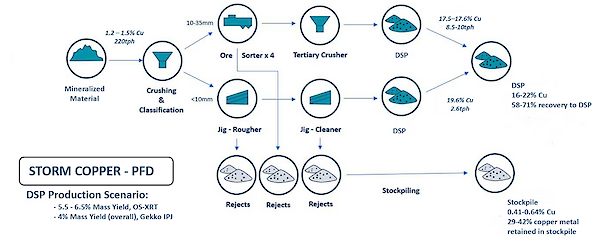
A generalized Process Flow Diagram (Figure 10) is provided for the selected, third option.
Figure 10: PFD for the Storm copper mineralization using a two circuit ore sorting and IPJ targeting a copper DSP product. The process can be optimized to achieve a targeted DSP grade, metal recovery or metal output.
The DSP processing test work was completed on each of the Cyclone and Chinook Deposits. For the Cyclone Deposit, feed grades at 1.2% to 1.5% Cu produced a 16-22% Cu concentrate with 58-62% of copper metal reporting to the DSP. For Chinook, feed grades at 1.2% to 1.5% Cu produced a 16-22% Cu concentrate with 64-71% of copper metal reporting to the DSP.
DSP PROCESS DESCRIPTION
The DSP process was broken down into 6 discreet process areas for the concept study.
Crushing and Classification Screening
The design feed rate for the circuit is a nominal 300tph excluding design allowance. This allows the circuit to feed the ore sorter station at full “name plate” capacity which mitigates the risk of high utilization requirements. The operating philosophy below titled “Primary Ore Sorting” details the operational advantages.
The ROM mineralized rock is received at the bin and is then fed into the jaw crusher by a Variable Speed Drive (VSD) controlled grizzly vibe feeder. The grizzly allows a nominal < 50mm to bypass the crusher. The crusher and grizzly outputs report to a two-deck classification screen. The three outputs of the classification screen are:
• Oversize: > 35mm recycled back to secondary crusher station;
• Middlings: ore sorter circuit feed. (154 tph, and 198tph at name plate); and,
• Fines: <10mm to Gekko fines upgrade. (66tph, and 85tph at name plate)
Primary Ore Sorting
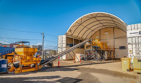
The ore sorter circuit configuration is based on 4 ore sorters on an N+1 redundancy basis. However, the option to run all 4 sorters at name plate capacity provides significant additional production capacity. Should a unit require down time for service or repair, it can be taken offline whilst the remaining three continue to operate to maintain nominal throughput.
The mineralized rock is delivered to a primary hopper which has two outputs and delivers the feed to two secondary hoppers. The outputs are VSD, or variable frequency drive (VFD) controlled to provide an optimum feed to the sorters. Stock “Nexus” samplers are located at the transfer points from the hopper outputs / sorter feed conveyors, and at the post sorter outputs for the ejected DSP material, and the reject material.
Ore Sorter Outputs
The sorter circuit has two outputs which are consolidated into collection conveyors that pass under the four sorter units. As the DSP product yield is significantly lower than the rejects, the DSP material is ejected, with the reject material passing as a “gravity” reject.
The ejected DSP material feeds into a feed surge bin.
Figure 11: Photo of a Steinert KSS KLI XT ore sorter and feed bin. Source: Steinert.
Feed to Fines (in-series IPJ) or Direct to Product loading
If the sorter output grade meets the DSP product specification, the option to bypass the in-series jigging is facilitated by a diversion chute. The bypass product output conveyor is the “battery” limit of the concept study.
The fines are fed to the in-series IPJ and are pumped from the hopper by injecting 40 to 60 m3 of hutch water at 2 to 3 bars.
Gekko Fines Upgrade
The classification screen <10mm fines that are pumped from the hopper, report to a rougher. The Gekko IPJ 2400 rougher outputs are DSP feed particles that directly load in-series to a Gekko IPJ1000 cleaner, with the rejects reporting to a collection hopper via a cyclone to be pumped to a dewatering screen. The cyclone is used to create back pressure to maintain the throughput control.
The cleaner IPJ DSP material reports to a collection hopper via a cyclone, and is then pumped to a dewatering screen, with the rejects added to the feed for the hopper.
(Layout recommendation: It is recommended that the option to locate the IPJs output feed directly to the dewatering screens to potentially eliminate the hoppers / pumping whilst retaining the cyclones).
Figure 12: Photo of a Gekko Inline Pressure Jig (IPJ). Source – Gekko.
Dewatering Screens
Two dewatering screens are assigned for the rejects and DSP respectively. Poly decks are nominally sized at a 1.2mm passing, which can be reduced to 500µ (0.5mm) if needed to limit the potential losses of product to slimes. The dewatering screen oversize material is conveyed to the DSP out-loading (battery limited) circuit, and via a dewatering screen to the ejects handling conveyor.
Desilters
Floc blocks are positioned at the inputs to increase settling performance if required. The desilters skids include peristatic pumps for auto-discharge of the sub-1.2mm “sludge” on a timer and fed to collection hoppers for downstream addition to loadout pending grade or eject to the discharge stockpile. The volumes are low and a “blend” feed to stockpiles should be considered. The water is recycled back to a makeup water tank which then feeds to the hutch inputs at the feed hoppers (for pumping and make up at the IPJs).
Fines Upgrade, Ore Sorter Select
The circuit is a duplicate of the fines upgrade circuit described above; however, the feed is the DSP from the ore sorters via the tertiary crusher (which delivers a <10mm (P80 passing) suitable for jig processing). The feed rates are similar at 61 at 220tph ROM feed and 80tph at name plate feed. The outputs reporting as do the fines upgrade jigging (IPJ) circuit.
Air Services
The compressor station is relatively stock, with the air supply criteria consistent with the ore sorter OEM specified requirements which are of instrument air standard. The pressure (design) is 10bar and the requirement summarized as follows:
• Particle content: Class 3
• Vapour content Class 4
• Oil Content Class 2
The compressor station redundancy is 2 + 1, with fridge drier bypass facilities for maintenance periods. The latter is less critical as a function of primary and secondary air receivers. The output manifold includes a plant air supply for the operations of the auto-sampler stations (x 7) and an optional knife feed (x 4) located at each sorter input to mitigate any dust carried into the sorter.
Samplers
The circuit includes seven samplers located to take samples at upgrade stations (particle and fines) input and outputs. The sampler stations are PLC controlled with preset (commissioning) size and frequencies. The latter can be set to local, manual sample tricker pending operational preferences.
